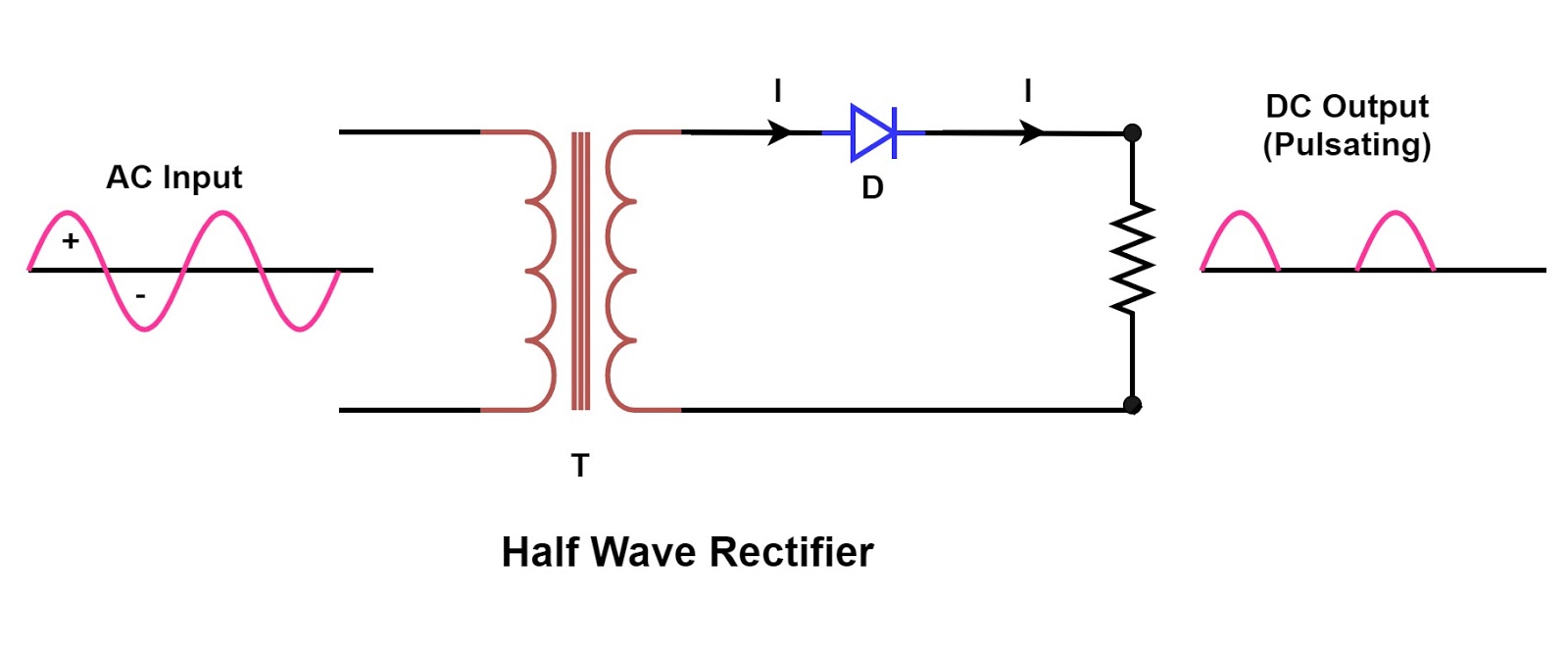
Draw the circuit diagram of full wave bridge rectifier and give its Full wave rectifier circuit working and theory Rectification explained part 1: half-wave rectification full wave rectification circuit diagram
With Neat Circuit Diagram And Waveforms Explain The Operation Of Full
What is full wave rectifier ? What is full wave rectifier ? Schematic structure of the full-wave rectifier under study.
What is single phase full wave controlled rectifier? working, circuit
Full wave rectifier basics, circuit, working & applicationsFull wave rectification diagram Rectifier disadvantages advantages electronicscoachFull wave rectification diagram.
In-depth guide to full wave rectifierIn-depth guide to full wave rectifier Center tapped full wave rectifier circuit diagramFull wave rectification diagram.
![Full Wave Rectifier Circuit Working and Theory](https://i2.wp.com/www.elprocus.com/wp-content/uploads/2015/01/21.jpg)
With neat circuit diagram and waveforms explain the operation of full
Full wave controlled rectifier circuit diagramHalf & full wave rectifier Rectifier circuit diagramRectifier wave bridge full circuit diagram diode voltage operation fig its shown below inverse peak disadvantages value when negative.
Rectifier wave circuit full theory capacitor working load rl voltage do bridge diagram calculate output half dc its typesอัลบั้ม 104+ ภาพ วงจร เรียง กระแส แบบ เต็ม คลื่น full wave rectifier Rectifier waveformRectifier advantages disadvantages electronicscoach.
![In-Depth Guide to Full Wave Rectifier - Circuit Diagram, Waveform](https://i2.wp.com/www.tutoroot.com/blog/wp-content/uploads/2023/03/e2-300x300.png)
Full wave bridge rectifier
Rectifier wave full circuit half bridge basics ac dcFull wave rectification circuit .
.
![What is Full Wave Rectifier ? - Circuit Diagram, Working, Advantages](https://i2.wp.com/electronicscoach.com/wp-content/uploads/2017/08/Center-tap-full-wave-rectifier-630x350.jpg)
![Full Wave Bridge Rectifier - its Operation, Advantages & Disadvantages](https://i2.wp.com/circuitglobe.com/wp-content/uploads/2015/12/FULL-WAVE-BRIDGE-RECTIFIER-FIG-5-compressor.jpg)
![Full Wave Controlled Rectifier Circuit Diagram](https://1.bp.blogspot.com/-NLikSO8goCQ/XsuVmIxdbGI/AAAAAAAAC40/DtPRAneVEIsh1lkv2vjdhUcYMRHdbJehwCLcBGAsYHQ/s1600/Rectifier-Page-6.jpg)
![Rectifier Circuit Diagram | Half Wave, Full Wave, Bridge - ETechnoG](https://1.bp.blogspot.com/-bTCLeh50vOE/YO6z8d2H3zI/AAAAAAAABMs/w7vO2Gw8nTcJVMMKq1r3cBeyP8caaUywwCLcBGAsYHQ/s16000/Half%2BWave%2BRectifier%2BCircuit%2BDiagram.png)
![Full Wave Rectifier Basics, Circuit, Working & Applications](https://i2.wp.com/how2electronics.com/wp-content/uploads/2022/09/Full-Wave-Bridge-Rectifier.jpg)
![Half & Full Wave Rectifier | Converting AC to DC | Rectifier Basics](https://i2.wp.com/www.electronicsforu.com/wp-contents/uploads/2017/08/full-wave-rectifier-circuit.png)
![With Neat Circuit Diagram And Waveforms Explain The Operation Of Full](https://i2.wp.com/hi-static.z-dn.net/files/d65/55a63d31a4bab5aca51706c080c1389f.jpeg?strip=all)
![Center Tapped Full Wave Rectifier Circuit Diagram](https://1.bp.blogspot.com/-ph3wPcxTMhg/YO60L9F14dI/AAAAAAAABM0/svLo3j9BnrEtn4_4Ldv94ZgxqVJXvAE7ACLcBGAsYHQ/s1035/Center%2BTap%2BFull%2BWave%2BRectifier%2BCircuit%2BDiagram.png)
![full wave rectification diagram - Wiring Diagram and Schematics](https://i2.wp.com/www.electroduino.com/wp-content/uploads/2021/04/Full-Wave-Bridge-Rectifier-–-Circuit-Diagram-and-Working-Principle.jpg)
![Rectification Explained Part 1: Half-Wave Rectification - Technical](https://i2.wp.com/eepower.com/uploads/thumbnails/featured-image-rectification-explained-part-1-half-wave-rectification.jpg)