Techpicz: functional block diagram of ne555 Ic 555 pinouts and working explained 555 timer – a complete basic guide functional block diagram of ic 555
555 Pinout
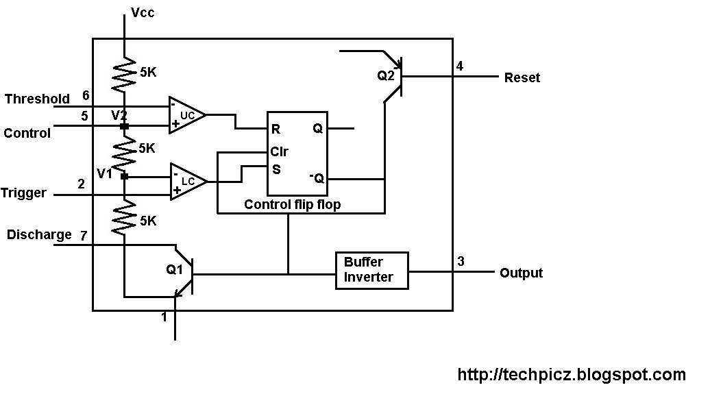
10+ functional block diagram of ic 555 Internal circuit of 555 timer 555 ic lm555 timer ne555 diagram internal schematic block pinout modified fairchild pinouts working ne556 control failure robot pcb following
555 timer ic block diagram working functional principle internal circuit schematic comparator avr pic ready help
Ic 555 circuit diagramIc 555 pin configuration Ic timer555 timer ic blockschaltbild internes ne555.
Functional block diagram of 555 timerIc 555 applications, pin diagram, internal circuit diagram explained Functional block diagram of 555 timerReady to help: functional block diagram of ic 555.

A complete basic tutorial for 555 timer ic
555 timer icDiagram block functional ne555 Ic 555 pinouts, astable, monostable, bistable modes explored555 timer ic diagram block basic circuit complete op principle circuits working projects tutorial guide flip two flop has collection.
Ic 555 diagram timer astable internal block ic555 ne555 circuits integrated modes bistable monostable explored pinoutsTimer block pinout modes من الجهد 555 timer ic block diagram working functional principle internal circuit schematic comparator avr pic ready help555 timer ic.
Block diagram of ic 555
555 timer ic working principle, block diagram, circuit, 49% off555 timer ic diagram block basic circuit complete principle op circuits working projects guide flip tutorial two flop has ece Functional block diagram of 555 timer555 timer tutorial.
Functional block diagram of 555 timer555 timer diagram ic block chip transistor tutorial discharge multivibrator does circuit logic electronics flop flip monostable bistable mode projects Ready to help: functional block diagram of ic 555555 timer circuit.

555 timer ic
555 timer schematic symbol .
.


